Data grading: (rated) = manufacturer specification · (typical) = commonly observed industry range · (cited) = published standard or industry reference · (illustrative) = approximate reference, not measured data

Introduction
Two operations questions cause more unplanned downtime and membrane damage in industrial water treatment than any others: changing cartridges too late, and sizing too few of them.
Change out too late and the element exceeds its rated differential pressure. At that point the media unloads — releasing captured particles back into the stream — or the core collapses, opening a direct bypass path. Either outcome sends a slug of contamination to the RO membranes or process equipment immediately downstream.
Size too few elements for the actual flow and clean DP is already elevated at startup. Service life is short, change-out frequency is high, and the element count never had a chance of delivering the interval the plant was designed for.
This guide covers both. It explains how to read and trend differential pressure correctly, how to set a defensible change-out criterion, how to calculate the number of cartridges your flow rate requires, and how to recognise and prevent cartridge collapse before it happens.
## Key Takeaways
- Differential pressure without a simultaneous flow reading is meaningless. Log both every time. DP alone tells you nothing about whether the element is loading, bypassing, or undersized.
- The clean DP baseline is the most important number you will ever record. Everything else — rate of rise, change-out criterion, service life projection — is calculated from it.
- Change-out on DP, not calendar. A calendar interval ignores feed water variability. An element that should last 90 days may be exhausted in 30 during a seasonal algae bloom.
- The change-out DP must include margin below the element’s collapse rating. Running to the collapse limit risks unloading captured solids into the downstream system.
- Flow per element is the primary sizing variable. Exceeding the recommended flow per element shortens element life roughly with the square of the flow ratio and raises clean DP immediately.
- A sudden DP drop on a loaded element is a collapse event, not recovery. It means the structural integrity of the element has failed. Shut down and inspect immediately.
- Cartridge telescoping is caused by exceeding the rated DP. The outer media layers separate from the core. The element must be replaced — a telescoped element cannot be re-used.
1. What Differential Pressure Tells You — and What It Does Not
Differential pressure (DP) across a filter cartridge stage is the pressure difference between the inlet and the outlet of the housing, measured in bar or psi.
Inlet pressure (P₁)  →  [Filter housing]  →  Outlet pressure (P₂)

DP = P₁ − P₂
What DP tells you
- Whether the element is loading. As solids accumulate in the media, hydraulic resistance increases and DP rises at constant flow.
- Whether the element is oversized or undersized for the flow. High clean DP at startup means the element count is insufficient for the actual flow rate.
- Whether a sudden event occurred upstream. A step increase in DP rate often correlates with a media filter backwash, a chemical upset, or an algae bloom.
What DP does not tell you
- Whether the element is bypassing. Bypass reduces DP (some flow takes a shorter path) or keeps it artificially low. A low DP reading with poor downstream water quality is the classic bypass signature.
- What the foulant is. Gelatinous foulants (coagulant floc, biological slime) and crystalline foulants (iron oxide, calcium carbonate scale) produce different DP curve shapes but similar endpoint values.
- Whether the element has collapsed. After collapse, DP may fall suddenly. The drop looks like improvement — it is a system failure.
Rule: always record DP and flow simultaneously. DP normalised to a constant flow rate is the only meaningful trend. A DP reading taken during a flow excursion or during a partial shutdown is not comparable to normal operating data.
2. Clean DP: The Baseline You Must Record
The clean differential pressure is the DP across a new, unused element at a known flow rate under normal operating conditions.
This number must be measured and logged at every element change-out, immediately after startup with fresh elements and before significant loading has occurred. It is the reference from which everything else is calculated.
Typical clean DP ranges
| Format | Rating | Flow per element | Typical clean DP |
|---|---|---|---|
| Standard 2.5 in OD, 40 in, melt-blown PP | 5 µm nominal | 1.5 m³/h (6.6 gpm) | 0.07–0.15 bar (1–2.2 psi) (typical) |
| Standard 2.5 in OD, 40 in, pleated PP | 5 µm nominal | 2.0 m³/h (8.8 gpm) | 0.05–0.10 bar (0.7–1.5 psi) (typical) |
| High flow 6 in OD, 60 in, gradient density | 5 µm nominal | 60–80 m³/h (264–352 gpm) | 0.10–0.25 bar (1.5–3.6 psi) (typical) |
If clean DP at startup is significantly higher than the values above for your element type, one of three things has happened: flow per element exceeds the recommended rate, the wrong micron rating was installed, or the element received a loading event during installation (e.g., flow was not diverted before the housing was opened).
Why clean DP matters for change-out
Most change-out criteria are expressed as a DP rise above clean — for example, "replace when DP reaches clean DP + 1.5 bar" rather than an absolute DP value. This is the correct way to set the criterion because it accounts for the fact that clean DP varies with flow rate. An absolute threshold (e.g., "replace at 2 bar") may trigger prematurely at low flow or dangerously late at high flow.
3. DP Growth Rate: Reading the Curve Shape
The rate at which DP rises over a service cycle is as informative as the endpoint value.
Curve shapes and what they mean
Steady linear rise:
DP
 |              /
 |           /
 |        /
 |     /
 |___/_____________ time
Solids are loading progressively into the depth media structure. This is normal behaviour for a correctly selected and sized depth filter. The element is being used efficiently.
Early steep rise followed by flattening:
DP
 |    /‾‾‾‾‾‾‾‾‾‾‾
 |  /
 |/________________ time
Surface blinding — solids are accumulating on the outer face rather than penetrating the media. Dirt holding capacity is being wasted. The micron rating may be too tight for the foulant character, or the foulant is gelatinous and compressible (coagulant floc, biological slime).
Sudden step increase:
DP
 |            |
 |            |
 |____________|____ time
An upstream upset event: media filter backwash fines, coagulant slug, or algae bloom. The step corresponds to a discrete event, not progressive loading.
Sudden drop on a loaded element:
DP
 |         /\
 |       /    \___
 |     /
 |___/_____________ time
Collapse. The element core or media pack has failed structurally under DP. The drop is not recovery — it is a bypass event. Shut down, pull the element, and inspect immediately. This is covered in detail in section 6.
4. When to Replace a Filter Cartridge: Setting the Change-Out Criterion
4.1 DP-based change-out (recommended)
The standard industrial practice is to change cartridges when DP reaches a defined threshold. Two threshold methods:
Method A — absolute DP limit:
Set the change-out point at a specific DP value, below the element’s rated maximum DP with margin.
Typical industrial practice: change-out at 1.5–2.5 bar (22–36 psi) (typical). The element’s rated maximum DP is typically 3–5 bar (44–72 psi) for a standard PP melt-blown element (rated, typical PP element). Setting change-out at 1.5–2.0 bar provides 1.5–3 bar of margin below collapse — enough to absorb a flow excursion without reaching the structural limit.
Method B — DP rise above clean:
Change-out when DP exceeds clean DP by a defined increment.
Example: clean DP = 0.1 bar; change-out at clean DP + 1.5 bar = 1.6 bar. This method is flow-rate independent and is more reliable when flow varies across the service cycle.
For RO pretreatment specifically, the downstream consequence of late change-out (membrane fouling) justifies conservative thresholds. A 1.5 bar rise above clean is a reasonable starting point for most SWRO and BWRO guard applications (typical).
4.2 Calendar-based change-out (secondary method only)
Replacing on a fixed calendar interval — monthly, quarterly — is acceptable only as a maximum interval backstop, not as the primary criterion. The problem with calendar-only change-out:
- Feed water quality varies seasonally. An element that lasts 90 days in winter may be exhausted in 30 days during a summer algae bloom.
- Flow rate changes (plant expansion, demand variation) alter loading rate.
- A calendar interval derived from average conditions underprotects during peak loading and overwastes during low-loading periods.
If a plant has no DP instrumentation, a calendar interval is better than nothing. But the interval should be set conservatively (shorter than average measured life) and reviewed seasonally.
4.3 SDI and downstream water quality triggers
For RO pretreatment, SDI₁₅ measured directly downstream of the cartridge stage provides an additional trigger independent of DP. If SDI rises above your membrane manufacturer’s feed specification while DP is still within range, the element may be bypassing or the upstream process may have deteriorated. Either requires investigation, not simply an early element change.
5. Cartridge Filter Sizing: How Many Elements Do You Need?
5.1 The fundamental variable: flow per element
The number of cartridge elements required for a given duty is set by one variable: maximum flow per element. Each element format has a recommended flow range; exceeding it causes:
- Elevated clean DP (varies roughly with the square of flow rate)
- Reduced contact time and lower effective removal efficiency
- Shorter service life, because surface velocity is higher and the element loads faster per unit volume
Typical recommended flow rates per element:
| Element format | Recommended flow per element | Notes |
|---|---|---|
| Standard 2.5 in OD × 10 in | 0.5–1.0 m³/h (2.2–4.4 gpm) | (typical) |
| Standard 2.5 in OD × 20 in | 1.0–1.5 m³/h (4.4–6.6 gpm) | (typical) |
| Standard 2.5 in OD × 40 in | 1.4–2.0 m³/h (6.2–8.8 gpm) | (typical) |
| High flow 6 in OD × 20 in | 30–60 m³/h (132–264 gpm) | (typical, duty dependent) |
| High flow 6 in OD × 40 in | 50–80 m³/h (220–352 gpm) | (typical, duty dependent) |
| High flow 6 in OD × 60 in | 70–115 m³/h (308–506 gpm) | (typical, duty dependent) |
Always confirm against the specific manufacturer’s datasheet for the element series and micron rating being used. Tighter micron ratings (1 µm vs 5 µm) have higher clean DP at the same flow and require a lower flow-per-element budget.
5.2 Element count calculation
Step 1 — Establish the design flow rate.
Use peak flow, not average. The cartridge stage must not be the bottleneck at maximum plant output.
Step 2 — Select the element format and length.
Based on housing available (or to be designed). For flows above ~50 m³/h, high flow 6 in OD elements are normally more economical in lifecycle cost. For flows below ~20 m³/h, standard 2.5 in × 40 in is typical.
Step 3 — Divide design flow by recommended flow per element.
Number of elements = Design flow (m³/h) ÷ Recommended flow per element (m³/h)

Round up to the nearest whole number.
Example — Standard 2.5 in × 40 in at 5 µm:
Plant design flow: 30 m³/h
Recommended flow per element: 1.5 m³/h (typical)
Elements required: 30 ÷ 1.5 = 20 elements
A 20-element housing (or two 10-element housings in parallel) is the minimum. In practice, size to the next standard housing configuration above the minimum to allow for flow growth and to provide margin if one housing needs to be isolated for maintenance.
Example — High flow 6 in × 60 in at 5 µm:
Plant design flow: 500 m³/h
Recommended flow per element: 90 m³/h (typical)
Elements required: 500 ÷ 90 = 5.6 → 6 elements
Six high flow elements replace what would otherwise be approximately 330 standard 40 in elements. One housing vessel of 6 elements versus 17 housings of 20 elements each.
5.3 Verifying the sizing: clean DP check
After installation, measure clean DP at design flow. If actual clean DP is significantly higher than the typical range for the selected element, flow per element is too high — add elements.
If clean DP is very low, elements are oversized for the flow. This is not a problem for filtration performance, but it may mean the element is seeing very little loading and calendar-based change-out is unnecessarily frequent.
6. Filter Cartridge Collapse: Causes, Recognition and Prevention
6.1 What collapse is
Every cartridge element has two DP ratings:
- Rated maximum operating DP — the DP at which the element is designed to operate continuously. Typical value: 3–5 bar (44–72 psi) for standard PP melt-blown (rated, typical).
- Collapse / burst DP — the DP at which structural failure occurs. Tested per ISO 16889 or equivalent. Typically 2–3× the operating DP for a well-constructed element (cited, ISO standard for filter element collapse/burst pressure verification).
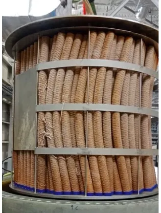
When DP exceeds the collapse rating, the inner core of the element buckles inward (collapse) or the outer media separates from the core (telescoping). Either mode creates a direct bypass path from inlet to outlet.
6.2 Telescoping
Telescoping is the axial displacement of the outer media wrap relative to the inner core, caused by the axial component of the pressure force when DP is high. The outer layers slide along the core, creating a gap at one end cap where unfiltered fluid passes directly through.
Telescoping is most common in:
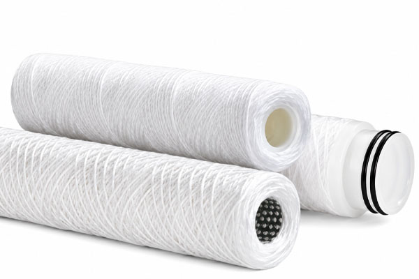
- Wound or wrapped media construction (string-wound, resin-bonded wound)
- Elements without a sturdy anti-telescoping device (ATD) on both end caps
- Elements operated well past their rated DP
A telescoped element may still produce a low DP reading because the bypass gap has low resistance. Downstream water quality is severely degraded. Inspection of the pulled element makes the diagnosis immediately: the media is visibly shifted axially, with a gap at one end.
6.3 Core collapse
The inner core is the structural backbone of the element. On outside-in flow (the standard for depth elements), the net pressure force acts radially inward on the core. If DP exceeds the core’s rated collapse pressure, the core buckles, creating a direct axial channel for unfiltered flow.
Core collapse is identifiable on inspection: the core is visibly deformed inward, and the end caps may be distorted.
A reinforced core — constructed from heavier-wall polypropylene tubing or perforated stainless steel — has a higher collapse DP rating and is specified for high-pressure applications such as SWRO pretreatment and condensate polishing.
6.4 Prevention
Set change-out DP with margin below the element’s rated maximum.
If the element is rated to 3.5 bar (51 psi) operating DP, set change-out at 2.0 bar (29 psi) or less. The margin absorbs flow excursions (pump starts, demand spikes) without reaching the structural limit.
Use a differential pressure switch or transmitter with an alarm.
A manual DP gauge read during scheduled rounds will not catch a rapid DP excursion between readings. An automatic alarm at the change-out DP threshold protects the element and the downstream system.
Protect against flow surges on pump start.
A sudden pump start can produce a brief DP spike several times the steady-state value. Slow-opening control valves or staged pump starts reduce this risk.
Specify elements with a reinforced core for demanding applications.
In SWRO, condensate polishing and other high-pressure or continuous-duty applications, specify elements with a rated collapse DP appropriate for the worst-case operating condition, not just the normal design DP.
Recognise a sudden DP drop as a collapse event.
Train operators that a DP reading that falls sharply on a loaded element is not good news. Shut down, pull an element, inspect, and replace the full set.
7. ECOFILTRONE Filter Cartridges: DP and Structural Specifications
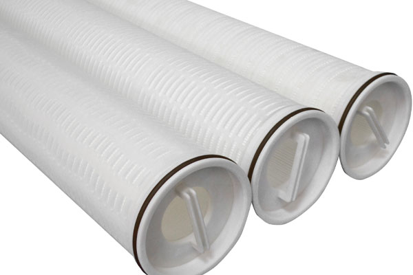
ECOFILTRONE High Flow Filter Cartridge (6 in OD)
Gradient density polypropylene depth construction with reinforced core rated for high-pressure RO pretreatment and condensate polishing service. Available in 20, 40 and 60 inch lengths; 1–20 µm nominal; DOE and SOE 226 double O-ring end caps; EPDM and fluoroelastomer seals.
Rated maximum operating DP: confirm from product datasheet for the specific series.
→ View DP ratings and structural specificationsECOFILTRONE Standard Filter Cartridge (2.5 in OD)
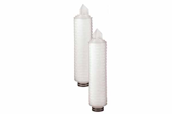
Melt-blown gradient density polypropylene; 10, 20, 30 and 40 inch lengths; 1–100 µm nominal; DOE and SOE 222/226 end caps. For general industrial and RO guard duty where flow per element is within the standard range.
→ View DP ratings and structural specifications
When selecting elements for applications where DP excursions are possible — high-pressure systems, systems without automatic DP alarming, or applications with variable feed quality — ECOFILTRONE can advise on the appropriate core construction and collapse DP rating for your operating conditions.
8. Putting It Together: A Practical DP Management Protocol
This sequence applies to any cartridge filtration system, from a 10-element conventional housing to a high flow multi-vessel train.
At every element change-out:
- Record inlet pressure, outlet pressure and flow rate before opening the housing (loaded DP baseline).
- Inspect pulled elements — note foulant depth, element condition, any deformation.
- Install new elements; confirm end cap seating.
- Restart slowly; record inlet pressure, outlet pressure and flow rate within 15 minutes of stable flow (clean DP baseline for this cycle).
- Log both values with date, time and flow rate in a running record.
During normal operation:
- Read and log DP with flow rate at every scheduled maintenance round — daily for critical applications, weekly for less critical.
- Plot DP against operating time (not calendar time) to generate the loading curve.
- Calculate the DP growth rate from the last cycle and compare it to previous cycles at the same time of year.
Change-out trigger:
- Replace when DP reaches the defined threshold (clean DP + 1.5 bar, or absolute threshold, whichever is more conservative for your application).
- Replace immediately if DP drops sharply on a loaded element — do not wait for the scheduled round.
- Replace early if downstream SDI or turbidity rises unexpectedly, even if DP is within range.
Review after each cycle:
- Did service life meet the target interval? If consistently shorter: investigate upstream chemistry or add elements. If consistently longer: the element may be oversized, or the calendar backstop is being triggered before the DP limit.
- Is the DP growth rate accelerating cycle over cycle? This indicates upstream process deterioration, not cartridge degradation.
9. Frequently Asked Questions
What is the normal differential pressure across a cartridge filter?
Clean DP for a correctly sized conventional 40 in × 2.5 in element at its recommended flow rate is typically 0.07–0.15 bar (1–2.2 psi) (typical). High flow 60 in × 6 in elements typically show 0.10–0.25 bar (1.5–3.6 psi) clean (typical). If startup DP is significantly higher than these ranges, flow per element is too high.
When should I replace my filter cartridge?
When DP rises 1.5–2.5 bar (22–36 psi) above the clean DP baseline at your normal operating flow rate (typical industrial practice). A calendar interval is an acceptable backstop but should not replace DP-based monitoring. If you have no DP gauges, a conservative quarterly interval is better than none — but install gauges as a priority.
Why is my filter pressure drop rising faster than expected?
The most common causes are: coagulant carryover from an upstream dosing upset, media filter breakthrough after a backwash, a seasonal algae or TEP event, or an element micron rating tighter than the duty requires. Check the upstream process before changing the element specification.
How do I calculate how many filter cartridges I need?
Divide the peak design flow (m³/h) by the recommended flow per element for the format you are using. For standard 40 in × 2.5 in elements, 1.4–2.0 m³/h per element is typical. Round up. Size to the next standard housing configuration above the minimum to provide operational margin.
What flow rate can a single filter cartridge handle?
A standard 40 in × 2.5 in melt-blown element handles approximately 1.4–2.0 m³/h (6–8.8 gpm) (typical). A high flow 60 in × 6 in element handles approximately 70–115 m³/h (308–506 gpm) (typical). Both figures depend on micron rating, media type and acceptable clean DP. Always confirm from the manufacturer’s datasheet for your specific element.
What causes a filter cartridge to collapse?
Exceeding the element’s rated maximum differential pressure. The most common causes are: running too long past the change-out DP, a flow surge on pump start, and an undersized element count that produces a high steady-state DP even on clean elements. A reinforced core construction and a conservative change-out threshold prevent most collapse events.
What is cartridge telescoping?
Axial displacement of the outer media wrap relative to the inner core, caused by DP exceeding the element’s rated limit. The media slides along the core, opening a bypass gap at one end. Identifiable on inspection — the media is visibly shifted. Telescoped elements must be replaced and the change-out criterion reviewed to prevent recurrence.
A sudden pressure drop occurred on a loaded element. Is that good?
No. A sudden DP drop on a loaded element almost always means the element has collapsed or the end cap seal has failed. Both produce a direct bypass path. Shut down, pull an element, and inspect before restarting. Do not continue operating on the assumption that conditions have improved.
Can I extend element life by reducing flow?
Yes — reducing flow per element lowers surface velocity, which reduces the rate of surface loading and flattens the DP growth curve. If service life is consistently shorter than the target interval and the upstream process is already optimised, adding elements to the housing (reducing flow per element) is the most reliable way to extend intervals.
What information do I need to size a cartridge filter system?
Peak design flow (m³/h or gpm), feed water analysis (SDI, turbidity, TSS, foulant type), upstream treatment (DMF or UF), target micron rating, target change-out interval, operating pressure and temperature, and whether the application is continuous or intermittent.
10. Discuss Your Application
If you are seeing high differential pressure at startup, cartridge life shorter than expected, or you are sizing a new cartridge stage and need to calculate element count and housing configuration, share your operating conditions — design flow, feed water analysis, current element type and your observed DP trend data.
ECOFILTRONE will review the data and advise whether the issue is element count, micron rating, upstream chemistry, or change-out policy, and propose a configuration suited to your target service interval.
WhatsApp: +86 131 8896 2285
Sources consulted: Boshart — pressure differential method for filter replacement · ISO 16889 / ISO collapse-burst standard · Chemical Processing — sizing cartridge filters · Industry DP and flow ranges (typical, multiple manufacturer datasheets).