How to correct the flow-pressure drop curve of a high-flow-rate filter cartridge for high-viscosity fluids?
Your pressure drop calculations are wrong, and you don’t know why. Your system is underperforming, and the pump is straining because your fluid is thicker than water.
To correct a pressure drop curve for a high-viscosity fluid, you must multiply the pressure drop value for water by a viscosity correction factor. The simplest and most common factor is the fluid’s viscosity in centipoise (cP) at its operating temperature.
I learned this lesson the hard way early in my career. I was helping a client who was filtering a type of hydraulic oil. They used the filter’s standard data sheet, which was based on water, to size their pump. When they started the system, the pressure drop was ten times higher than they expected, and the pump couldn’t keep up. The entire production line had to stop. That day, I realized that the numbers on a data sheet are just a starting point. You have to understand the fluid you are working with. The pressure drop curve is not a universal truth; it is a reference point that almost always needs adjustment for real-world conditions.
Why can’t I just use the standard water-based pressure drop curve?
You have the manufacturer’s chart right in front of you. It seems much easier to just use those numbers for your flow rate and move on with your project.
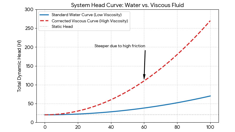
A standard curve is only for clean water, which has a viscosity of about 1 centipoise (cP). Using it for a fluid that is 100 times thicker will give you a pressure drop estimate that is 100 times too low.
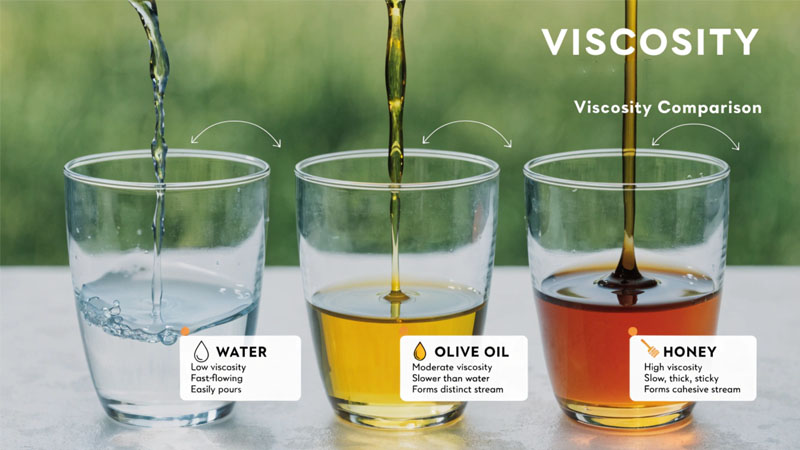
Using a water-based curve for a viscous fluid is like planning a road trip assuming your car gets 50 miles per gallon when it really only gets 20. You will run out of gas. In filtration, pressure drop is the force required to push a fluid through the filter media. Viscosity is a measure of a fluid’s resistance to flow. A fluid with high viscosity, like oil or syrup, is "thicker" and resists being pushed through the tiny pores of a filter much more than water does. This means your pump has to work much harder. The water curve represents a best-case scenario with the least resistant fluid possible. Ignoring viscosity will lead to massively undersized pumps, unexpectedly high operating pressures, and a system that fails to meet its required flow rate. It is a fundamental error that can have expensive consequences.
How do I find the correct viscosity correction factor?
You know you need a correction factor, but where does it come from? You need a reliable number to make an accurate calculation for your system design.
The correction factor is simply the fluid’s viscosity value in centipoise (cP) at your specific operating temperature. You can find this value from the fluid’s data sheet or by measuring it with a viscometer.
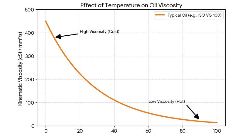
This is the most critical step. The viscosity of a liquid changes a lot with temperature. For example, honey is extremely thick when cold but flows easily when warm. The same is true for industrial oils, chemicals, and resins. You cannot use the viscosity value at room temperature if your process runs at 80°C.
Here is the simple, step-by-step process I teach engineers:
- Find the "clean water" pressure drop (ΔP) on the manufacturer’s chart for your desired flow rate. Let’s say it’s 2 psid for a 100 GPM flow.
- Determine the viscosity of your fluid in centipoise (cP) at its operating temperature. Look at the fluid’s technical data sheet or use a viscometer. Let’s say your oil at 60°C has a viscosity of 50 cP.
- Multiply. The corrected pressure drop is the water pressure drop multiplied by the viscosity.
In our example:
Corrected ΔP = 2 psid (from water) × 50 cP (the correction factor) = 100 psid.
The initial pressure drop isn’t 2 psid; it’s 100 psid. This is a huge difference and shows why this calculation is essential for correctly sizing your system.
Does this correction factor work for all filter types and flow rates?
This seems almost too simple. You wonder if this basic multiplication rule has limits or if it’s safe to use for every situation you encounter in the field.
This simple viscosity correction is very accurate for liquid filtration under laminar flow conditions, which covers most industrial applications. It becomes less accurate for turbulent flow (very high velocities) or for compressible fluids like gases.
The reason this simple multiplication works so well is that within the fine, porous structure of a filter cartridge, the fluid moves in a smooth, layered way. This is called "laminar flow." In a laminar flow regime, the pressure drop is directly proportional to the fluid’s viscosity. Double the viscosity, and you double the pressure drop required to maintain the same flow rate. This linear relationship makes our calculation reliable.
However, there are edge cases. If the flow rate is extremely high, the flow in the pipes and housing around the filter might become turbulent or chaotic. In turbulent flow, the relationship between viscosity and pressure drop is more complex. But for most engineers like Jacky designing process filtration systems, the flow inside the filter media itself is the dominant factor, and it remains laminar. This simple correction is a powerful and reliable tool for 95% of liquid filtration scenarios. The main thing to remember is that this rule is for liquids only. Correcting for gases involves entirely different formulas.
Conclusion
To accurately predict pressure drop, multiply the filter’s clean water pressure drop by your fluid’s viscosity in centipoise (cP) measured at the actual operating temperature. It is a simple but critical calculation.