How to Calculate the Exact Number of High-Flow Filter Cartridges Required
Rapid Answer
Calculating the required number of high-flow filter cartridges seems straightforward: divide your Total System Flow Rate by the Maximum Rated Flow per Cartridge.
However, in professional process engineering, this basic arithmetic is a trap. If you size a housing based solely on a manufacturer’s theoretical "maximum flow rate" (often advertised as 80 to 110 cubic meters per hour or 350 to 500 GPM per 60-inch element), the system will likely suffer from catastrophic pressure spikes and premature failure in the field.
To calculate the exact and reliable number of cartridges, you must move away from the theoretical maximum and calculate the Optimized Operational Flux. This requires derating the cartridge capacity based on three critical fluid variables: Viscosity, Micron Rating, and Total Suspended Solids (TSS) load.
The Baseline Formula: The Theoretical Calculation
The foundational equation for sizing a filter array is:
Number of Cartridges = Total Flow Rate / Optimized Flow Capacity
Total Flow Rate = Total system flow rate (m3/hr or GPM).
Optimized Flow Capacity = The adjusted, derated flow capacity per individual cartridge.
The engineering challenge lies entirely in determining the "Optimized Flow Capacity". A high-flow cartridge advertised at 80 m3/hr is only capable of that flow rate under laboratory conditions: pumping clean municipal water at 20 degrees Celsius through a coarse 20-micron media.
The Engineering Reality: The 4 Derating Pillars
To find your true optimized capacity, you must aggressively derate the laboratory maximum based on the physical reality of your specific fluid.
Pillar 1: Viscosity Derating (The Friction Factor)
Water has a viscosity of 1 centipoise (cP) at 20 degrees Celsius. If your fluid is highly viscous (e.g., amine, heavy naphtha, or lubricating oil), the hydraulic friction through the micro-pores increases exponentially.
Engineering Rule: If viscosity doubles, initial differential pressure (Delta P) doubles. You must reduce the per-cartridge flow rate proportionally to maintain a safe initial Delta P.
Pillar 2: Micron Rating Derating (The Permeability Factor)
A 1-micron absolute pleated filter has significantly smaller and tighter pores than a 20-micron filter. Tighter pores mean less open area for fluid to pass through, resulting in higher resistance.
Engineering Rule: Pushing 80 m3/hr through a 1-micron filter will cause an immediate Delta P spike. For sub-micron or 1-micron absolute retention, maximum flow per element is often derated by 30% to 50%.
Pillar 3: Contaminant Matrix (TSS & Solid Type)
If you operate a filter at its maximum rated flow, the fluid velocity (flux) through the pleated media is extremely high. High velocity physically forces deformable solids (like biological gels, oil emulsions, or shear-sensitive Iron Sulfide) straight through the media, causing "extrusion bypass."
- Engineering Rule: For heavy solid loads or gelatinous contaminants, dropping the flux rate (by adding more filters) reduces the impact velocity, allowing the media to capture and hold the dirt rather than shearing it.
Pillar 4: Target Clean Initial △P
The golden rule of filtration economics: Never design a system where the clean initial △P exceeds 0.15 to 0.2 bar (2 to 3 psi). If you size the system with too few filters, you might start with an initial △P of 0.6 bar. Because pressure rises exponentially as the filter plugs, starting at 0.6 bar means you have already consumed 70% of the filter’s usable life on day one.
Diagnostic Sizing Matrix: How to Derate
Use this cross-validation matrix to adjust your optimal flow away from the advertised maximum.
| Process Variable | Real-World Condition | Sizing Action (Adjusting Capacity) | Engineering Rationale |
|---|---|---|---|
| Fluid Type | Heavy Hydrocarbons / Amine / Glycol | Derate by 40% – 60% (Target 30 – 45 m³/hr per 60-inch element) |
High viscosity rapidly elevates initial ΔP; lower flux prevents pressure alarms on start-up. |
| Filtration Target | 1-Micron or 2-Micron Absolute | Derate by 20% – 40% (Target 45 – 60 m³/hr per 60-inch element) |
Tight micro-glass media possesses higher structural resistance; reducing flow prevents pleat pinching. |
| Contaminant Type | Biological Slime / Soft Gels / FeS | Derate by 30% – 50% | Ultra-low flux is required to prevent deformable contaminants from extruding through the pores. |
| Water / Pre-RO | Clean Water, 10-Micron, Low TSS | Minimal Derating (Target 70 – 85 m³/hr per 60-inch element) |
The fluid closely matches laboratory baseline conditions. |
Field Experience: The Cost of "Mathematical Sizing"
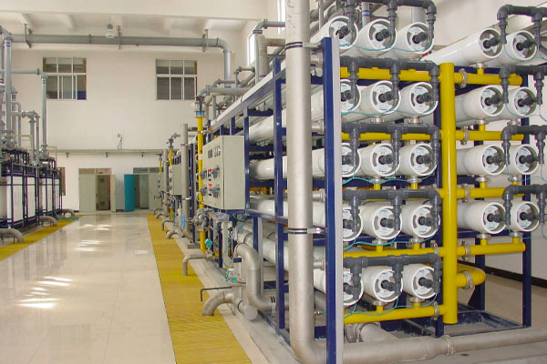
An EPC contractor designed a seawater reverse osmosis (SWRO) pre-filtration system for a flow rate of 1,200\m³\ hr They read a standard supplier brochure stating a 60-inch high-flow element handles 100 m³/hr .
Applying basic math ( 1200 / 100 = 12 ), they purchased a steel housing designed to hold exactly 12 elements.
During commissioning, the raw seawater experienced a seasonal algae bloom (high biological/gelatinous TSS). Because the 12 elements were running at absolute maximum velocity, the biological slime was driven deeply into the pleat roots instantly. The clean initial △P started at an unacceptable 0.4 bar, and the filters reached terminal pressure (plugged completely) every 4 days.
The plant had to shut down, cut the piping, and install a second, parallel 12-element housing. By doubling the number of filters to 24, the flow per cartridge dropped to a conservative 50 \m³\ hr . The initial △P dropped to 0.1 bar, the flux rate became gentle enough to hold the biological gels without crushing them, and the filter lifespan extended from 4 days to 45 days.
The ecofiltrone Engineering Sizing Strategy
When sizing a high-flow system, our engineering priority is Total Cost of Ownership (TCO), not just minimizing the initial capital cost of the steel vessel.
- Optimize the Flux, Don’t Maximize the Flow: We size systems to operate at a conservative flux rate. By adding 10% to 20% more cartridge capacity upfront, we drastically reduce the fluid velocity hitting the media.
- Ensure a 0.15 Bar Start: We mathematically model the specific gravity, viscosity, and micron rating of your fluid to guarantee the system comes online with an initial △P below 0.15 bar.
- The Lifespan Multiplier: Operating high-flow cartridges at 60% of their theoretical maximum flow rate often results in a 300% increase in dirt-holding lifespan.
By calculating the exact number of filters based on fluid reality rather than marketing maximums, we ensure that your high-flow retrofit delivers massive operational stability and a payback period measured in months, not years.