Why Old Power Plant Systems Use Traditional Meltblown Cartridges (And the Logic Behind High-Flow Retrofits)
Rapid Answer
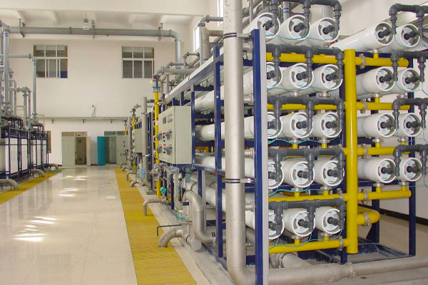
The use of massive arrays of standard 2.5-inch meltblown filter cartridges in older power plants is not a design flaw; it is a result of historical technological limitations. Decades ago, standard depth filtration was the most reliable and cost-effective method to achieve the required water purity for critical systems like condensate polishing and reverse osmosis (RO) pre-filtration.
Today, advanced pleated high-flow filter cartridges pack exponentially more surface area into a single element. Upgrading to high-flow technology allows plants to replace 400 standard filters with just 10 to 20 high-flow elements. This retrofit drastically reduces maintenance downtime, eliminates hundreds of potential bypass leak points, and increases dirt-holding capacity—all without having to cut or replace the existing steel pressure vessels.
The Historical Context: The "Brute Force" Engineering
When legacy power plants were built in the 1980s, 90s, and early 2000s, engineers faced a strict mathematical problem regarding flux (flow rate per unit of filter surface area).
- The Limitation of Depth Filters: Traditional meltblown cartridges are "depth filters." They trap particles throughout the thickness of their polypropylene walls. Because they are physically narrow (typically 2.5 inches in diameter), they have a very small surface area.
- The Flow Rate Problem: If you force a massive volume of water through a small filter, the velocity increases rapidly. High velocity causes the differential pressure ($\Delta P$) to skyrocket, which can push trapped dirt completely through the filter or cause the filter to collapse.
- The Array Solution: Because advanced pleated high-flow technology was either unavailable or prohibitively expensive at the time, engineers solved the flow-rate problem through sheer volume. If one standard 40-inch filter could only handle 1.5 m³/hr, processing 600 m³/hr required a massive steel housing containing 400 individual filter cartridges.
The Operational Pain Points of Legacy Systems
While these massive arrays work, they create severe operational and financial burdens for modern plant maintenance teams:
| Operational Challenge | The Reality of Traditional 2.5" Filters |
|---|---|
| Extreme Maintenance Downtime | Replacing 300 to 400 filters takes a crew of operators an entire shift (6 to 12 hours). During a critical path start-up, this downtime is incredibly costly. |
| High Risk of Fluid Bypass | Standard filters often use a Double Open End (DOE) knife-edge seal. A housing with 400 filters has 800 individual sealing points. If just one spring misaligns, dirty water bypasses the entire system, fouling expensive RO membranes or resins downstream. |
| Ergonomic & Safety Hazards | Operators must manually lean over open, wet housings to extract hundreds of heavy, water-logged cartridges. |
| Massive Waste Volume | Disposing of 400 filters generates a massive volume of solid waste, which is particularly expensive if the system is processing hazardous or chemically treated fluids. |
The Physics and Logic of High-Flow Retrofits
The transition to high-flow filter cartridges represents a shift from depth filtration to surface area filtration.
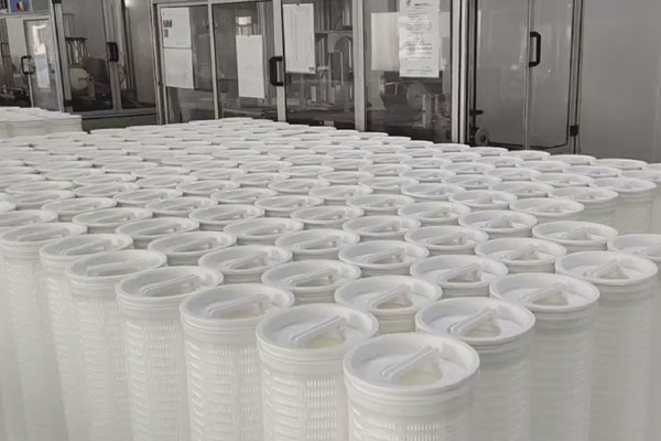
- Pleated Geometry: High-flow cartridges (typically 6 inches or 6.5 inches in diameter) utilize advanced pleated micro-glass or polypropylene media. By pleating the material, manufacturers can pack up to 8 square meters ($85 \text{ ft}^2$) of effective filtration area into a single 60-inch cylinder.
- The Replacement Ratio: Because of this massive surface area, one 60-inch high-flow cartridge can comfortably process 80 to 110 m³/hr. Mathematically, one high-flow element replaces the workload of 20 to 40 standard meltblown cartridges.
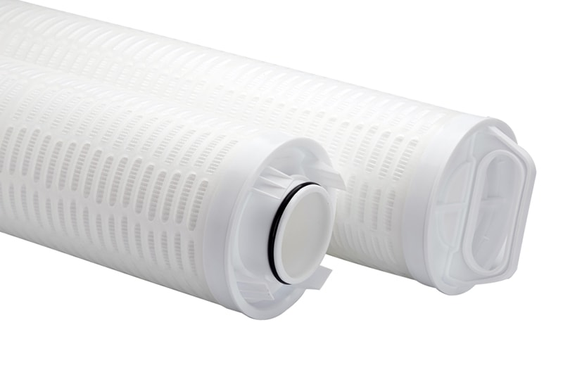
- Inside-Out Flow Dynamics: Standard filters flow from the outside in, meaning the dirt stays inside the steel housing when you remove the filter. High-flow cartridges are designed to flow from the inside to the outside. All the captured crud is trapped safely inside the core of the filter element, keeping the steel pressure vessel perfectly clean.
How Retrofit Solutions Actually Work (The Value Proposition)
When plant managers hear "upgrade," they often worry that they have to cut their pipes and install a brand new, expensive steel pressure vessel. This is not the case.
The core strength of a retrofit solution is that it utilizes the plant’s existing footprint.
The Retrofit Execution Process:
- Gut the Internals: During an outage, operators open the existing housing and remove the hundreds of old meltblown cartridges and their alignment posts.
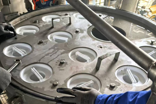
- Install the Adapter Plate: A custom-machined stainless steel "tubesheet" or adapter plate is bolted or welded into the existing housing.
- Insert High-Flow Elements: Instead of 400 filters, operators drop 10 to 15 high-flow cartridges into the new adapter plate. They lock into place with a secure, single O-ring seal.
The ROI of the Retrofit
By performing this retrofit, the power plant immediately achieves:
- 90% reduction in labor time (Change-outs drop from 8 hours to 30 minutes).
- 99% reduction in bypass risk (Sealing points drop from 800 down to 15, using positive O-ring seals).
- Extended Run Lengths (Pleated media offers superior dirt-holding capacity, extending the time between shutdowns).