Standard Operating Procedure (SOP): Troubleshooting Premature Filter Cartridge Exhaustion
Rapid Answer
When a customer complains that a newly installed filter cartridge "clogs in a few days" instead of its normal lifespan, field engineers must immediately shift the diagnostic focus away from the filter itself. A rapidly clogging filter is rarely defective; it is successfully doing its job by capturing an unexpected surge of contaminants.
Premature exhaustion—indicated by a rapid spike in differential pressure (△P)—is almost always a lagging indicator of an upstream process anomaly. The SOP for on-site troubleshooting requires a systematic investigation to rule out mechanical errors, verify fluid dynamics, and perform a physical "autopsy" on the exhausted cartridge to identify the root cause of the upset condition.
Phase 1: Pre-Site Data Collection (Remote Triage)
Before dispatching to the site or touching the equipment, establish the baseline. Customers often misdiagnose the problem, so you must secure the evidence.
- Quarantine the Evidence: Instruct the operators not to throw away the clogged cartridge. It must be preserved (preferably in a sealed plastic bag to retain moisture) for visual and chemical analysis.
- Verify the Part Number: Check the purchase order. Did procurement accidentally order a 1-micron filter instead of the standard 10-micron filter? A tighter micron rating will mathematically exhaust much faster.
- Request the $\Delta P$ Logs: Ask for the SCADA data or manual logs for the differential pressure and flow rate over the last 72 hours. Is the $\Delta P$ rising linearly, or did it spike vertically in a matter of minutes?
Phase 2: On-Site Mechanical & Installation Inspection
Once on-site, rule out the hardware and human error before diving into process chemistry.
- Gauge Calibration Check: Are the pressure gauges actually working? Mechanical gauges frequently stick, vibrate out of calibration, or fail due to internal corrosion. Tap the gauge or verify the reading with a calibrated handheld manometer. A false high $\Delta P$ reading simulates a clogged filter.
- Installation Verification: Was the filter installed correctly? If a cartridge is forced into a housing without proper seating, it can deform. However, note that an installation error (like a pinched O-ring) usually causes a bypass (zero $\Delta P$ and dirty fluid downstream), not premature clogging.
- Verify Valve Positions: Ensure all upstream and downstream isolation valves are fully open. A partially closed downstream valve creates artificial backpressure, which the system may misinterpret as a clogged filter.
Phase 3: Operational Dynamics & Process Review
If the hardware is sound, the fluid dynamics or process conditions have changed.
- Flow Rate Surges: $\Delta P$ increases exponentially with flow velocity. Did production increase? Did the operators start using two pumps in parallel instead of one? If the flow rate doubled, the filter’s dirt-holding capacity will be exhausted in a fraction of the normal time.
- Viscosity Shifts (Temperature): For viscous fluids (oils, resins, syrups), a drop in temperature drastically increases viscosity. Pumping cold, thick fluid through a filter will cause an immediate $\Delta P$ spike that mimics particulate blinding, even if the filter is completely clean.
- Upstream Upset Conditions: Interview the operators about activities prior to the clogging event:
- Was a tank bottom stirred up or agitated?
- Was a new batch of raw materials introduced?
- Did an upstream pre-filter fail or bypass, dumping its load onto this finishing filter?
Phase 4: The Filter Autopsy (Visual Diagnostics)
The clogged filter is the black box of the process. Extract it, cut it open if necessary, and examine the media. The physical state of the contaminant tells you exactly what failed upstream.
Contaminant Diagnostic Matrix
| Physical Appearance of Clogged Media | Diagnostic Inference (Root Cause) | Required Operator Action |
|---|---|---|
| Slimy, slick, or gelatinous coating | Biological/Organic Fouling: Algae, bacteria, or coagulant/flocculant overdosing upstream. Gelatinous material blinds the surface instantly without penetrating the depth of the filter. | Check biocide dosing or adjust upstream chemical coagulation rates. |
| Hard, crusty, or crystalline scaling | Precipitation: Changes in pH, temperature drop, or mixing incompatible chemicals caused dissolved solids to physically crystallize out of solution onto the filter media. | Review chemical dosing logs and monitor temperature stability to prevent precipitation. |
| Heavy, dense particulate (Rust/Sand) | Pipe Descaling / Upset: A hydraulic shock, valve hammer, or pump startup stripped a massive layer of scale or rust from the upstream piping network. | Flush the upstream lines. Consider installing a coarse bag filter housing upstream as a roughing stage. |
| Clean appearance but high $\Delta P$ | Viscosity / Hydrocarbon Blinding: Cold fluid viscosity, or aqueous filters being blinded by an unexpected influx of trace oils (emulsion block). | Check fluid temperature; verify oil/water separation stages upstream. |
Field Experience: Diagnosing the "Gelatinous Blind"
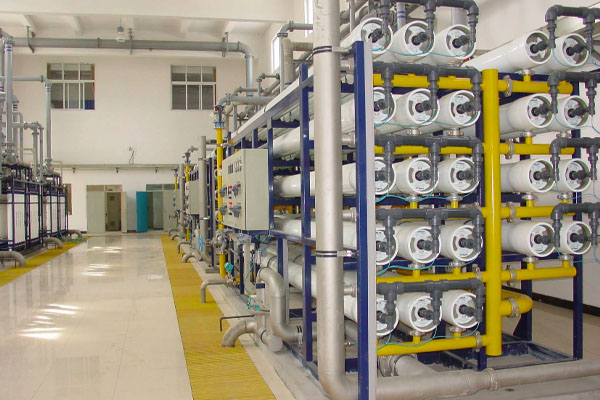
At a reverse osmosis (RO) desalination plant, operators complained that their 5-micron melt-blown pre-filters were suddenly blinding every 48 hours, down from a normal lifespan of 3 weeks. The procurement team was preparing to return the entire batch of filters to the manufacturer.
Upon conducting the on-site SOP, the field engineer performed an autopsy on the exhausted cartridge. Instead of the usual brown silt, the filter was coated in an invisible, slippery, clear gel.
By cross-referencing this finding with the plant’s chemical dosing logs, the engineer identified the true root cause: the plant had recently switched to a new liquid coagulant to treat the incoming seawater. However, the dosing pump had not been calibrated for the new chemical’s higher concentration. The system was severely overdosing the coagulant, creating massive polymer chains that formed a gelatinous sheet over the filter cartridge.
The filters were doing exactly what they were designed to do—protecting the multimillion-dollar RO membranes from polymer fouling. Once the coagulant dosing pump was recalibrated, filter lifespan immediately returned to 3 weeks.
Conclusion & Corrective Action Strategy
When concluding the troubleshooting visit, guide the customer to one of three corrective actions based on the autopsy:
- Fix the Upset: If the blinding is due to a transient event (e.g., tank stirring, chemical overdose), correct the upstream process. The filter consumption will naturally normalize.
- Add a Pre-Filtration Stage: If the contaminant load is the "new normal" for the plant, the current filter is doing too much work. Recommend installing a cheaper, coarser pre-filter (like a 50-micron bag filter or strainer) upstream to absorb the bulk load, saving the expensive finer cartridges.
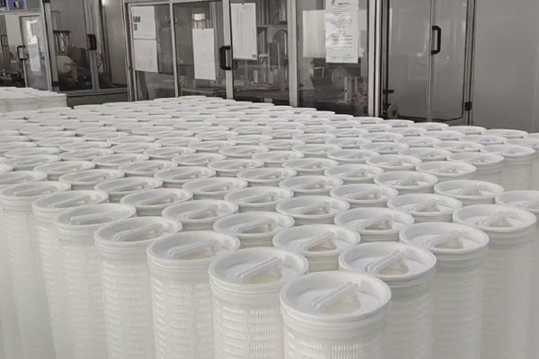
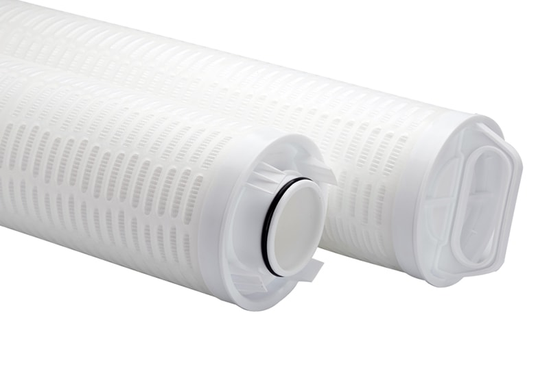
- Upgrade the Filter Structure: If the fluid requires high flow and contains high solids, recommend upgrading from standard depth cartridges to high-flow pleated structures, which possess exponentially higher dirt-holding capacity and surface area to handle heavy particulate loading.